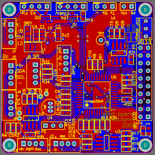
Connects to 128×64 LCD (sure electronics). Buffered DAC outputs. Some low side mosfets for fan/relay/LCD backlight control.
PCB render:
Schematic:
PDF: xmega_base.pdf
BOM: xmega_bom.xls (resistors not included, design not tested)
Main components:
Issues:
- There is a problem when a 5V LCD is used as xmega i/o is not 5V tolerant. Will need 3k series resistors on pins LCD_D0-7.
#002


Hi. I received two of your boards (#001 and #002) via ITead’s OpenPCB-service. Is there a bill of materials available? This #002 looks like a generic prototyping board for the XMega-series, right? I’d like to assemble and test it out.
Cool, even before me 🙂
It should be fairly generic. Connectors are a mix of 2mm/0.1″. Also the program header is non-standard but its only 4 pins.
I’ve updated the post with a PDF schematic. I will add a BOM within a day.